
Futaba
FP-S136G For J, M, SG and CONQUEST Series
FP-S36G for E, F, G, H and L Series
High quality low height landing gear servo
The FP‑S136G and
FP‑S36G are double ball‑bearing landing gear servos designed
and manufactured for use with Futaba radio control sets. The FP‑S136G is for the
Futaba J, M, SG and CONQUEST Series and the FP‑S36G is for the E, F, G, H, and L
Series
[FEATURES]
* A new low height (1.00 in/25.4mm) landing gear servo to be installed in main wing.
* Low height
water‑tight and dust‑tight servos using a high quality five‑pole micromotor.
Output torque: 76.4oz‑in (5.5kg‑cm) Nominal Operating speed 0.50 sec/60°
* Forward and
reverse rotation controlled by pulse width by turning a transmitter snap switch
on and off.
Rotation stops at the full throw position in either direction.
* Low current drain. Motor drive current does not flow when stopped even if a light load is applied such as other digital proportional servos.
* Fiberglass reinforced PBT (polybutylene terephthalate) injection molded servo case is mechanically strong and invulnerable to glow fuel.
* Strong polyacetal resin precision servo gear and metal gear ensure smooth operation with virtually no backlash.
* Fiberglass reinforced epoxy P‑C board with through‑the‑hole plating improves servo amp vibration and shock resistance.
* Thick film
gold plated connector pins eliminate faulty contact and increase reliability
against shock and vibration.
The S136G connector housing has a reverse insertion prevention mechanism.
* 3 P mini connector permits replacement with existing Futaba set. (S36G)
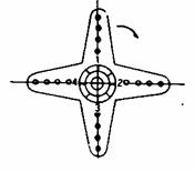
* Four adjustable (splined) servo horns.
[RATINGS]
Control aystem ............................. +pulse width control
Operating angle ............................ One side approx 160*
Power supply ............................... 4.0‑6.OV, shared with receiver
Current drain ................................ 6.OV 8mA (at idle)
Output torque ............................... 76.4oz‑in (5.5 kg*cm)
Operating speed ........................... 0.50 sec/60° (nominal)
Dimensions .................................. 1.78 X 0.89 X 1.00 in (45.2 X 22.7 X 25.4mm)
Weight ......................................... 1.47 oz (42g)
[PRECAUTIONS]
[ ] Use the S136G with Futaba J, M, SG and CONQUEST Series RC sets and the S360 with E, F, G, H, and L Series sets. These servos can not be used with other brand RC sets.
[ ] Match the landing gear stroke and landing gear servo stroke exactly and connect the linkage so the landing gear is not raised or lowered past the limits of the
[ ] When using screws, install the servo with grommets and tighten the screws so the grommets is slightly crushed. If the screws are too tight, the cushioning effect of the grommets will be lost.
[ ] A spare horn is supplied. Use as needed. (Ratings and other specifications are subject to change without notice.)
|
No. |
Part name |
Part No. |
|
1. |
Upper case |
FCS-36G |
|
2. |
Middle case |
FCS-36G |
|
3. |
Bottom case |
FCS-36G |
|
4. |
Ball bearing |
S04130 |
|
5. |
TR-133-150 |
I39620 |
|
6. |
Binding head tapping screw |
J55016 |
|
7. |
VR drive plate |
S02753 |
|
8. |
Motor |
S91248 |
|
9. |
Motor pinion |
S02497 |
|
10. |
1st gear |
FGS-36G |
|
11. |
2nd gear |
FGS-36G |
|
12. |
3rd gear X 2 |
FGS-36G |
|
13. |
5th gear |
FGS-36G |
|
14. |
Final gear |
FGS-36G |
|
15. |
1st shaft |
S03260 |
|
16. |
Pin B |
S01345 |
|
17. |
Intermediate shaft |
S02495 |
|
18. |
Seal ring |
S90415 |
|
19. |
Spacer washer 0.3T |
S02486 |
|
20. |
O-ring |
S90420 |
|
21. |
Servo horn D |
FSH-6W |
|
22. |
Horn mounting screw |
FSH-4I |
|
23. |
S136G Printed wiring board |
AS1324 |
|
S 36G Printed wiring board |
AS1325 |
|
|
24. |
S136G 3PB-WRB-300 |
FPC-8M |
|
S 36G 3PC with cord |
FPC-3M |
|
|
25. |
Lead wire packing |
S90045 |
|
26. |
O-ring |
S90410 |
|
27. |
Case mounting screw |
J50051 |
|
28. |
S136G Name Plate |
S60158 |
|
S 36G Name Plate |
S60157 |
SPLINED HORN
This horn permits
shifting of the servo neutral position at the servo horn side. Setting and
shifting the neutral position.
a)
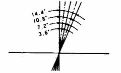
Angle division
1) The number of segments per spline is 25. The amount of change per segment is 360/25 = 14.4°.
2) The minimum adjustable angle is determined by the number of arms or number of axes of the holes.
For four arms, 360° / (25 x 4) = 3.6°
b) Effect
1. Baseline A
To shift the holes center line to the right (clockwise) relative to baseline A. shift arm 2 to the arm 1 position arm set it to the position closest to the basline A.
[Example] For a four arm horn the angular shift per segment is 14.4°. The shift to the right is 90° - (14.4° x 6) = 3.6°. To shift by the same angle in the opposite direction, use the opposite arm number.
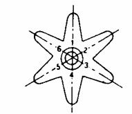
For a six arm horn, to shift the holes center line to the right (clockwise) relative to base line A, turn the arm counterclockwise and set arm 2 to the position of arm 1. The adjustable angle is 60° - (14.4° x 4) = 2.4°
Arm 3 shifts 4.8° to the right and arm 6 shifts 2.4° to the left and arm 4 shifts 7.2° to the right and left.
FUTABA CORPORATION OF AMERICA
4 Studebaker, Irvine California 92718, U.S.A.
Phone: 714‑455‑9888 Telex: 23‑0691227 Facsimile: 714‑455‑9899
FUTABA CORPORATION
Makuhari Techno Garden Bldg., B6F 1‑3 Nakase, Mihama‑ku, Chiba 261‑01, Japan
Overseas Marketing & Sales Radio Control Systems
Phone: (043)296‑5119 Facsimile: (043)296‑5124